A multipurpose card that emulates ROM and RAM. The ROM content is loaded from the SD card, as well as single-part programs in machine code stored in the CAS format. Below I provide a complete guide on how to make own Flexi Card.
Introduction
Flexi card (hereinafter FC) would probably never have been created if I had not come across the pages of Kernelcrash1, who inspired me with his projects and from which FC is based. Some parts of his code are used in my project without changes. I thank KernelCrash for not keeping his knowledge to himself, and for allowing me to draw on his experience. Therefore, I am also making this project available to others.
Hardware
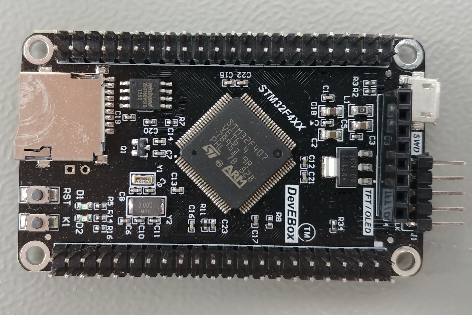
FC uses a Chinese development board DevEBox.2 The advantages of this board are its small size, low price3, the presence of a slot for a micro SD card. It has a large number of IO ports and, most importantly, and this is also the reason for choosing this processor, that most of its GPIO ports are 5V tolerant, which is essential for cooperation with TTL logic. It is also very easy to flash and contains a debug port. The heart of this board is the STM32F407 processor from the Arm Cortex-M4 family2. Specifically, the VET6 variant, which has 512 KB of Flash memory3. It goes without saying that the use of a development board is not essential for the project, if you are able to design your own PCB with a minimal circuitry of the processor plus the necessary components for the operation of the SD card. I chose a development board, which is more convenient for prototyping and contains everything necessary.
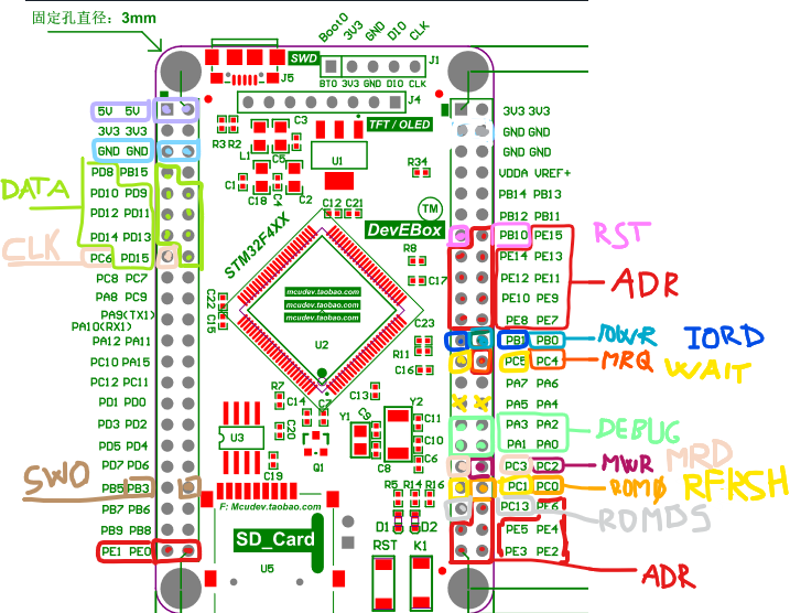
Pin wiring
The choice of pins used seems messy, but it should be pointed out that each pin in the STM serves several functions that are activated/deactivated in software. So it depends what peripherals you want to use.
Sord
GPIO pin
IOWR
PB0
IORD
PB1
RFSH
*PC1
WAIT
PC5
RST
PB10
MRD
PC3
MWR
PC2
ROMDS
PC13
ROM0
PC0
MRQ
PC4
CLK
*PC6
D0..D7
PD8-PD15
A0..A15
PE0-PE15
* marks pins not yet used in fw
used by FLASH
/CS
PA15
MOSI
PB5
SCK
PB3
MISO
PB4
used by SWD
SWDIO
PA13
SWCLK
PA14
SWO
PB3
user LEDS
LED1
PA1
used by SD
DAT2
PC10
DAT3
PC11
CMD
PD2
CLK
PC12
DAT0
PC8
DAT1
PC9
debugging output (not used in normal mode except PA1 for LED) PA0-PA3
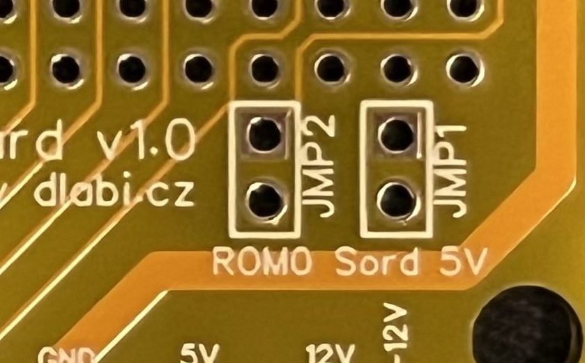
Important: The FC power supply can be implemented in several ways. For the final operation, the board is ready to use the Sord's power supply. However, if you need flash or connect the FC using the STLINK dongle, you must first disconnect JMP1, otherwise you may damage the FC or Sord!
Function
After reset or power on, the FC tests for the presence of the SD card. If the sordm5 directory is found in the root, which is a kind of indicator that the SD card contains compatible programs, the presence of the menu.rom file in the root of the card is tested. If it is found, it is loaded at address 2000H (i.e. as a ROM cartridge) and run. This then shows the user the contents of the SD card and allows the user to select programs. Alternatively, if a file called debug.cas is found in the root, it is loaded into memory as well. I have often used this to debug z80 code.
If any of this testing fails, FC goes into Basic – F + 32kB RAM and the SD card is not used.
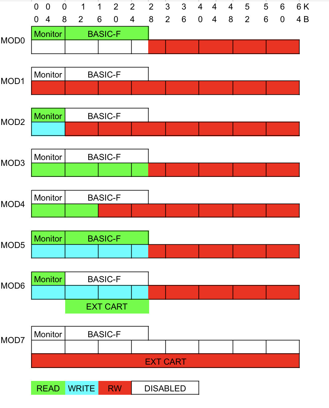
The program has a time-critical part written in arm assembler. This is the MREQ handler, where we emulate RAM and ROM. The rest is written in C, which is easier to write, although I personally don't like it, so please excuse any nonsense in the code. That being said, without the SD card, the FC behaves like a 64KBF DIY card (I may redo it in the future to a slightly different mode), which in the modified Sord4 allows you to reach up to 64kB of RAM by disabling the MONITOR ROM and the cartridge. In the unmodified Sord, of course, only 32kB. To prevent damage to the unmodified Sord, there is a ROM0 jumper on the FC which, when disconnected, prevents control of the ROM0 signal used to disable MONITOR ROM. The memory modes are controlled via port 30h as follows:
If a falling edge is detected on MREQ, an interrupt is generated, in which it is determined by reading the MWR and MRD signals whether it is a read or write to RAM or ROM memory. The time required to start the interrupt service routine is about 83nS and lasts ~583nS at the maximum processor frequency. Furthermore, it is determined according to the set memory mode whether the memory area is under the control of FC and whether it is a RAM type area in case of writing. Otherwise, the interrupt is quickly terminated to leave the processor time to the main thread.
This is formed by an infinite loop, in which the state of the variable main_thread_cmd is tested, which indicates whether Sord requires something from the FC card (or vice versa). This variable is set in the interrupt activated by the falling edge on IOWR, which is initiated by writing a command to port 81h. Then, depending on the command, data is sent or read on port 80h. Currently, FC recognizes these commands:
0
BREAK
Breaks current command
1
GET_COUNT
Returns the file count
2
SET_INDEX
Sets pointer position on file number
3
GET_INDEX
Gets pointer position
4
NEXT_FILE
Increase pointer position by 1
5
PREV_FILE
Decrease pointer position by 1
6
FIRST_FILE
Resets pointer
7
GET_FILENAME
Reads filename at pointer position from buffer
8
LOAD_FILE
Loads file to memory
9
RESET_SORD
Not implemented yet
10
DIR_SORD
Dirs SD card to buffer
11
OFFSET_RAM_ON
Offsets FC ram region 7000-7FFF to 8000-8FFF
12
OFFSET_RAM_OFF
Disables FC ram offset
Program menu.rom is written in z80 assembler. The program provides a list of programs located on the SD card in a pageable menu. After the user selects a program cmd8 is used to load the selected program into the RAM area. However, if the program is located in the area 7000-7fff, it is “covered” by the Sord's internal RAM. For these purposes cmd11 is used, which can temporarily offset the “covered" area by +1000h, i.e. to the area 8000-8fff. Then it is up to menu.rom to copy the data from here to the Sord's internal memory and then cancel the offset with cmd12 .This trick is mainly used for the MSX programs, where the MSX bios is located in the area 7000-7fff
Another task of the main loop is to test the RST signal. If its activity is detected, the duration of the press is recorded. If it is shorter than about 3s, only Sord is reset (FC does not react). If it is longer, FC is also reset. Another way to reset FC independently of Sord is to use the RST button under the SD slot.
For communication of FC with SD card, the open source library FatFs is used.5
Compilation
You will need the arm cross compiler. A description of how to get one for your platform is beyond the scope of this article. I use WSL, so the following description will use the Linux environment.
Next, you will need the firmware package for the STM32F4DISCOVERY board from st.com. It is called STSW-STM3206866, unzip it somewhere and set this directory in the Makefile in the STM_COMMON variable .
Then you will need the Basic-F rom, copy it to the roms directory, rename it to basic-f.rom. If you want to run MSX, you will also need msx.rom. Once you have everything together, follow these steps to start the compilation.
cd src
make
To compile menu.rom you will need the z80 cross compiler. I use pasmo7which you can install using
sudo apt install pasmo
And then you compile with the command
make menu
Firmware flashing
There are basically two ways to flash. Either via the built-in USB port in DFU mode, which you switch the card to by switching the BOOT0 pin from GND to 3V3. Then you connect to your computer and flash using the dfu-util8 on Linux with the make flash-dfu command, or using the DfuSe Demo for Windows. In this case you will need your compiled code in dfu format. To create the dfu format you can use this utility: hex2dfu9.
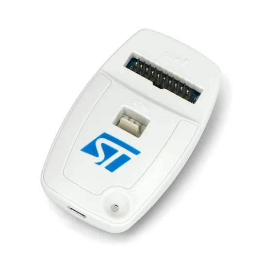
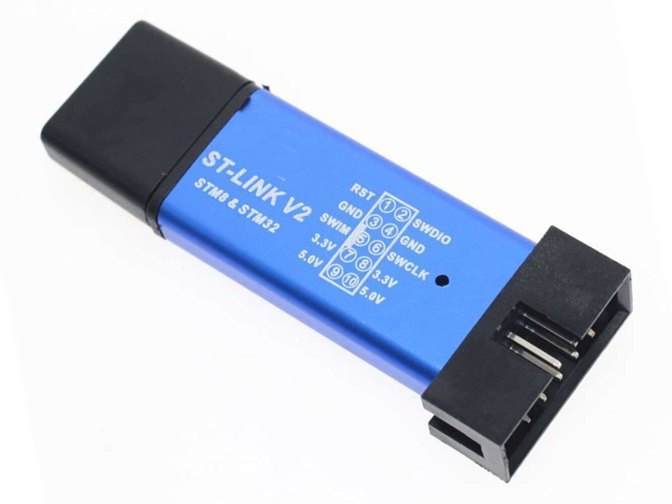
Original programmer
Chinese clone
The second way requires the STLINK programmer. In this case you don't need to switch BOOT0 at all, the programmer will do everything by itself. I used the Linux program st-flash10which you will run by command make flash.
SD card preparation
Format the card to FAT32 format. KernelCrash recommends cards with small capacity, or at least format them to a smaller size, because they are then less problematic. I have been using a 4GB card without any problems during testing.
Place menu.rom and optionally debug.cas in the root of the card. Create a directory here called sordm5 and copy the files you want to run into it. Remember, however, that the sorting is not alphabetical, but according to the order in which you wrote them to the card. To properly recognize the programs, you need to adjust the extensions of the programs as follows:
ROM or BIN: ROM cartridges
CAS: programs with autostart in machine code
MSX: MSX programs that run under MSX. They are stored in the classic CAS format.
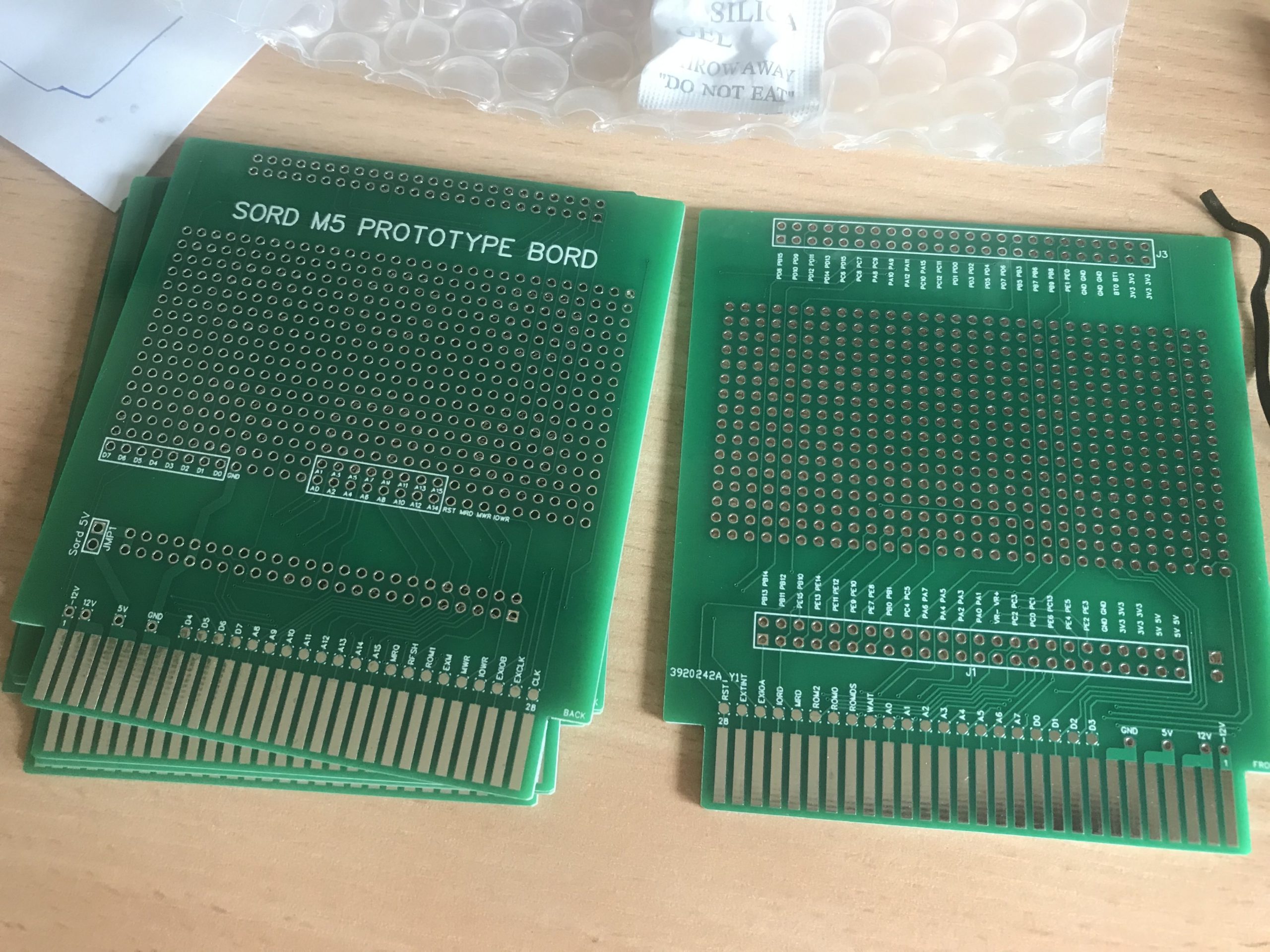
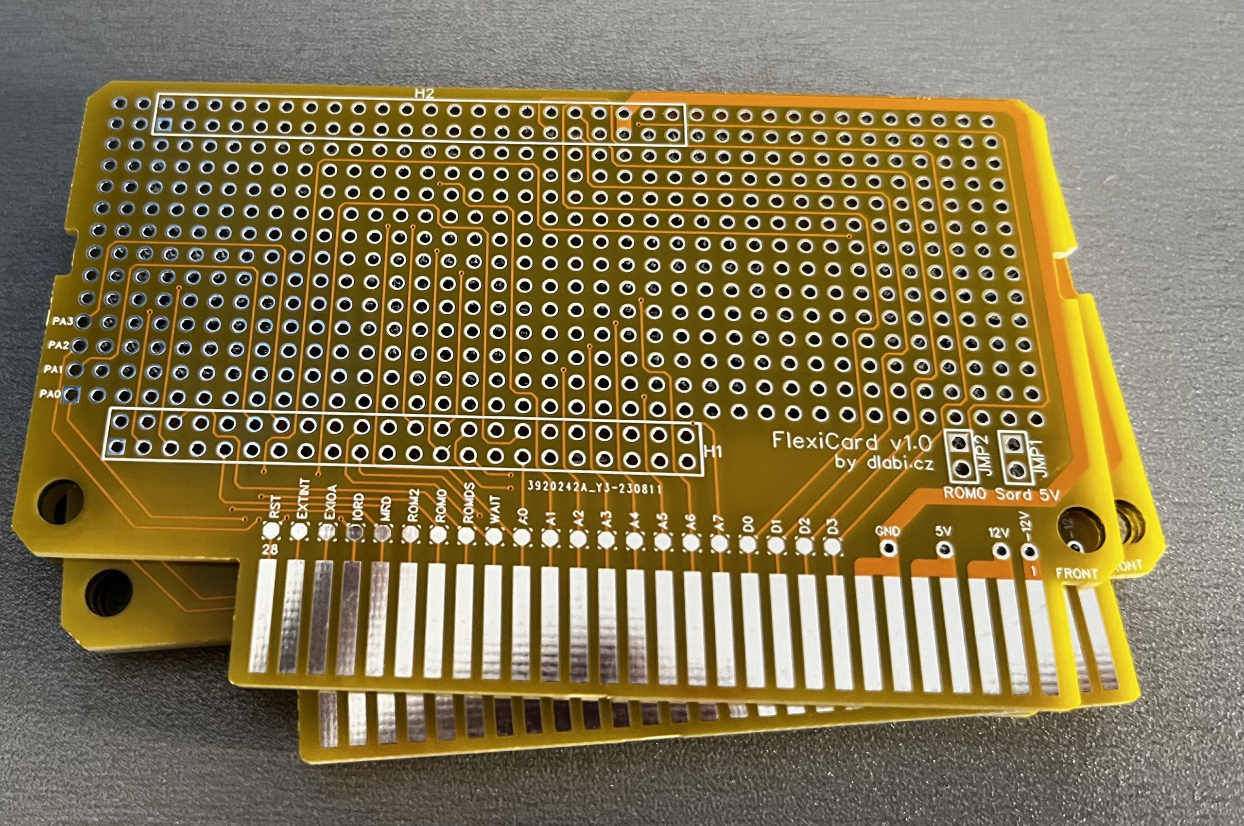
PCB fabrication
Well, it depends on where you want to make the board. I used PCB Prototype & PCB Fabrication Manufacturer – JLCPCB, you just need to use the Gerber file from the repository from the pcb folder and set the desired board properties. The minimum number of boards is 5 pieces, but the service is quite cheap, considering how much trouble it saves you.
There are many ways to use the potential of the STM board, so there is room for improvement. So far, FC can do the basics. Maybe in the future I will change the functionality a bit, depending on how the current solution works (or not).
If you would like me to elaborate or add something, write in the comments. And if you haven’t seen it yet, there is also a pseudo advertisement for Flexi Card which I've created for fun :-)
Jednoznacne se to pozna pouze rozebranim, nebo pokud vam to prodejce rekl. Neprimo byse to dalo poznat pokud Vam k romu prodal DIY pamet 64kb, ktera tuto modifikaci potrebuje.
pak vyuzijete Flexi Card naplno 😉 Nicmene zalezi jak na to pospichate, rad bych vam nabidl flexiCard v2, ktera je trochu predelana, ale casu je malo a neni to dotazene. PCB ma male zmeny, ktere nejsou zpetne kompatabilni, takze fw pro v1 nebude fungovat na PCB v2 a obracene. Hardwarove to je shodne. Dejte vedet co preferujete.
Zdravím, klidně si počkám, pokud je dokončení v řádu týdnů, či několika měsíců. Pošlete mi e-mail, až bude nová verze hotová. Z chatu mi nechodí upozornění na odpověď. Díky! S pozdravem RT
We use cookies on our website to give you the most relevant experience by remembering your preferences and repeat visits. By clicking “Accept All”, you consent to the use of ALL the cookies. However, you may visit "Cookie Settings" to provide a controlled consent.
This website uses cookies to improve your experience while you navigate through the website. Out of these, the cookies that are categorized as necessary are stored on your browser as they are essential for the working of basic functionalities of the website. We also use third-party cookies that help us analyze and understand how you use this website. These cookies will be stored in your browser only with your consent. You also have the option to opt-out of these cookies. But opting out of some of these cookies may affect your browsing experience.
Necessary cookies are absolutely essential for the website to function properly. These cookies ensure basic functionalities and security features of the website, anonymously.
Cookie
Duration
Description
cookielawinfo-checkbox-analytics
11 months
This cookie is set by GDPR Cookie Consent plugin. The cookie is used to store the user consent for the cookies in the category "Analytics".
cookielawinfo-checkbox-functional
11 months
The cookie is set by GDPR cookie consent to record the user consent for the cookies in the category "Functional".
cookielawinfo-checkbox-necessary
11 months
This cookie is set by GDPR Cookie Consent plugin. The cookies is used to store the user consent for the cookies in the category "Necessary".
cookielawinfo-checkbox-others
11 months
This cookie is set by GDPR Cookie Consent plugin. The cookie is used to store the user consent for the cookies in the category "Other.
cookielawinfo-checkbox-performance
11 months
This cookie is set by GDPR Cookie Consent plugin. The cookie is used to store the user consent for the cookies in the category "Performance".
viewed_cookie_policy
11 months
The cookie is set by the GDPR Cookie Consent plugin and is used to store whether or not user has consented to the use of cookies. It does not store any personal data.
Functional cookies help to perform certain functionalities like sharing the content of the website on social media platforms, collect feedbacks, and other third-party features.
Performance cookies are used to understand and analyze the key performance indexes of the website which helps in delivering a better user experience for the visitors.
Analytical cookies are used to understand how visitors interact with the website. These cookies help provide information on metrics the number of visitors, bounce rate, traffic source, etc.
Advertisement cookies are used to provide visitors with relevant ads and marketing campaigns. These cookies track visitors across websites and collect information to provide customized ads.


Dobrý den,
bylo by od Vás možné koupit kompletní Flexi Card, případně PCB.
S pozdravem
Rudolf Toužín
Dobry den,
PCB urcite ano, jeste me nejake zbyly. Kompletni Flexi Card nechci uplne slibovat, ale prinejhorsim by to slo tez.
EDIT: jeste se zeptam, mate Sorda upraveneho pro odepinani vnitrni ROM nebo vanilla?
S pozdravem
Ales Dlabac
Dobrý den,
právě jsem ho koupil, takže nemám zkušenosti. Jak poznám variantu?
S pozdravem
RT
Jednoznacne se to pozna pouze rozebranim, nebo pokud vam to prodejce rekl. Neprimo byse to dalo poznat pokud Vam k romu prodal DIY pamet 64kb, ktera tuto modifikaci potrebuje.
Paměť 64kb je součástí sestavy
Dobrý den, k Sordu mám originál cartridge EM-5 32kB a potom vyráběnou 64kB.
S pozdravem
Rudolf Toužín
pak vyuzijete Flexi Card naplno 😉 Nicmene zalezi jak na to pospichate, rad bych vam nabidl flexiCard v2, ktera je trochu predelana, ale casu je malo a neni to dotazene. PCB ma male zmeny, ktere nejsou zpetne kompatabilni, takze fw pro v1 nebude fungovat na PCB v2 a obracene. Hardwarove to je shodne. Dejte vedet co preferujete.
Zdravím, klidně si počkám, pokud je dokončení v řádu týdnů, či několika měsíců. Pošlete mi e-mail, až bude nová verze hotová. Z chatu mi nechodí upozornění na odpověď. Díky! S pozdravem RT
Dobrý den, je něco nového s flexiCard v2? S pozdravem RT
Dobrý den,
Bohužel ne, věnoval jsem se, co se Sorda týče, MAME emulátoru. Dám vám kdyžtak vědět, až se to posune. Děkuji za trpělivost
Díky!